W-AIR Network Admin Guide - Sync over the air
This guide leads you through the installation of W-AIR Base and W-AIR Base Outdoor and setting up a W-AIR DECT Network in which the bases sync over the air.
Updated: February 2022
Permalink: https://wildix.atlassian.net/wiki/x/SwrOAQ
Watch the video tutorial about setting up W-AIR Multicell Network (registration is required):

Description
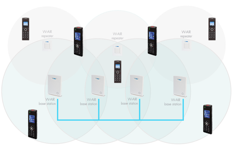
System architecture
W-AIR is a Wildix cordless solution. The system supports auto-provisioning enabling instant connection to the Wildix PBX. Due to high scalability, new components are quickly and easily integrated to guarantee better performance.
Wildix W-AIR system uses the wireless technology CAT-iq (Cordless Advanced Technology – Internet quality).
The architecture consists of three components:
1. Base station - an essential component of a DECT system. Wildix W-AIR base stations:
- Multicell base stations: W-AIR Base Sync Plus, W-AIR Base Sync Plus Outdoor (for sync over LAN, refer to W-AIR Network Admin Guide - Sync over LAN)
- Single Cell base station: W-AIR Base Small Business. Documentation: W-AIR Small Business - Admin Guide, /wiki/spaces/DOC/pages/30279971
2. Repeater - extends the signal coverage of the base station.
3. Cordless endpoints:
Wildix W-AIR handsets: W-AIR Basic2, W-AIR LifeSaver, W-AIR Med, W-AIR Office and W-AIR Headset. Follow the online Guides to get detailed information: W-AIR DECT Handset - User Guide, W-AIR Headset - User Guide.
Multicell network scalability and features
Sync over the air with W-AIR Base, W-AIR Base Outdoor or mixed network in which W-AIR Bases Sync Plus are present:
- Up to 1000 users per system
- Up to 250 bases
- Up to 30 handsets registered to one base station*
- Up to 3 Repeaters per base
- Up to 50 bases - 3 repeaters
- 50-125 bases - 1 repeater
- More than 125 bases - no repeater
- Up to 100 Repeaters registered to one system
- Up to 8 concurrent calls** per base
- 8 narrow band audio channels per base
- 4 CAT-iq wideband audio channels per base
- (Single cell setup) Max 10 concurrent calls per base
- Handover through the base station (max. 8 simultaneous handovers)
- Up to 5 concurrent calls per repeater
- Up to 24 sync levels
- Base station indoor range: 50 m; outdoor range: 300m
*Note: by default W-AIR system supports up to 20 devices, to increase the number to 30 devices, use Custom Provisioning parameter, described in this document: Provisioning Custom Settings.
** Enabling PTT feature (Push-to-talk) on W-AIR handsets reduces the number of available channels on each base station to 6.
Planning a multicell network
Before you start
Important:
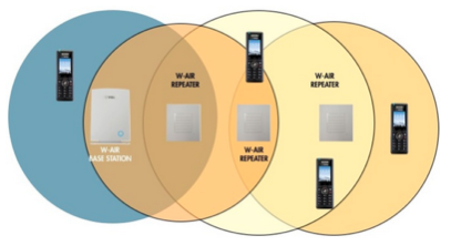
- Base stations can sync over the air only in case they are able to see each other.
- They see each other if the dBm value is between -75 and 0.
- Repeater which is placed between the two Base stations can only extend the coverage but cannot perform the sync.
Intelligent Networking Configuration:
Connecting 3 Repeaters in a chain:
Base Station and Repeater positioning:
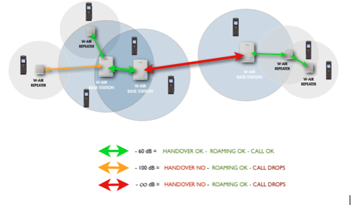
For a good conversation and a correct handover between Bases and Repeaters the dBm value must be between -75 and 0.
Handover and Roaming
Handover
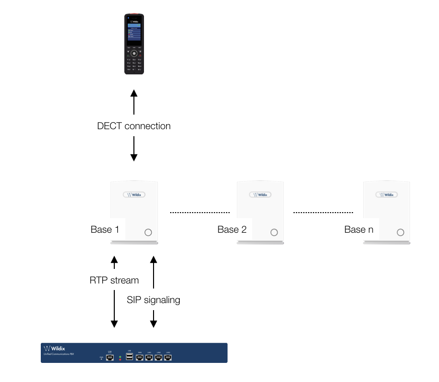
Handover is a process in which a call is transmitted from one base station to another without interrupting the session.
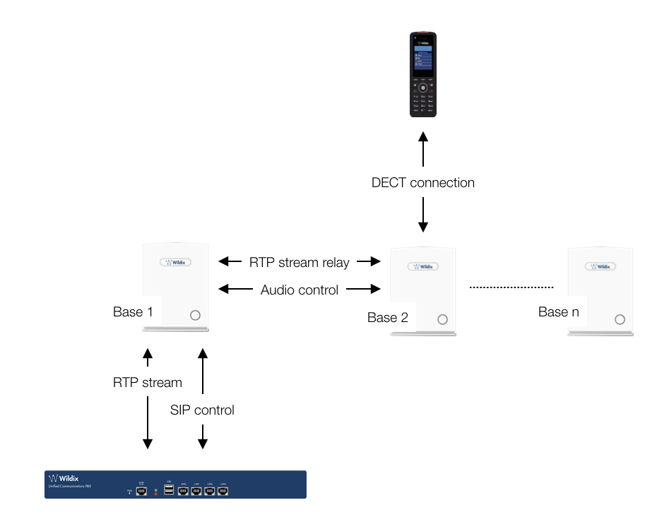
When the call is set up, the handset is located at Base 1. Thus, the DECT communication takes place between the handset and Base 1, and the SIP signaling as well as the RTP stream takes place between Base 1 and the PBX:
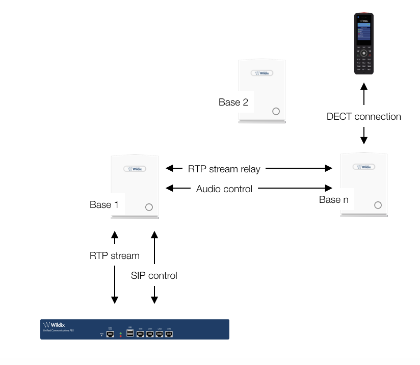
After handover, the handset is located at Base 2, and hence the DECT communication goes on between the handset and Base 2. However, to avoid disruption of the audio, the RTP stream is relayed via the initial base station, since a transfer of the RTP stream to another base may cause the PBX to re-initialize the RTP stream with a small disruption of the RTP stream as consequence. Thus, RTP stream is not affected by the handover, and since the call control also remains at Base 1, SIP signaling is also unaffected, as shown below:
Since the call control and hence the SIP User Agent remains at the initial base station, the SIP registration is also unaffected by the handover. If the handset makes yet another handover, the RTP stream will still be relayed via the base station at which the call was established (Base 1 in our case):
Roaming
By roaming it is meant that the handset moves its SIP and DECT registration from one base station to another base station. Roaming can only be initiated from idle.
Roaming does not immediately result in a new SIP registration, to avoid unnecessary signaling. Therefore, the handset will not perform a new DECT Location Registration until it has resided on the same base station for a defined period of time*. Since the SIP registration is initiated by the completion of the Location Registration, a new SIP registration will also not be done until this procedure has completed on a new base station. Thus, a handset must stay on the same base station before a new SIP registration is made.
*How the period of time after which Location Registration is performed, is defined:
Handsets lose contact to the initial base station due to reset/ power off/ heavy DECT traffic.
After 5 minutes but before 5+2 minutes (+2 minutes occur when service connection traffic is signalled at the same time as location registration should take place; in this case the location registration procedure will be delayed)
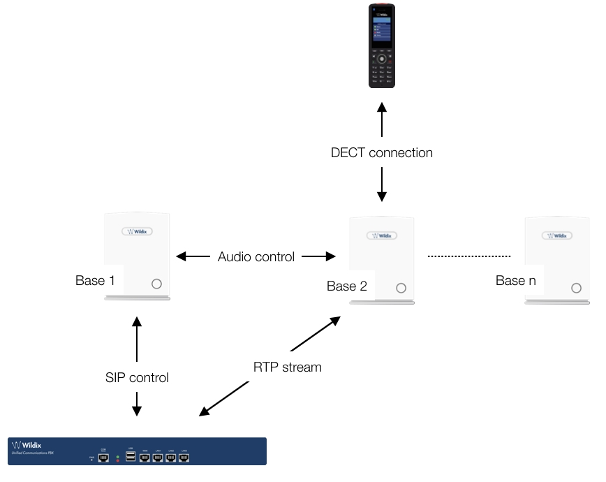
If an incoming call arrives while the handset has moved to another base station (Base 2 in our example) but the new Location Registration was not yet performed, the SIP call will arrive at the initial base station (Base 1 in our example), the RTP stream will be set up between Base 2 and the PBX. Alternatively, in the case of an outgoing call, the SIP call will be established from the initial base station, and the RTP stream will be set up between Base 2 and the PBX:
Deployment considerations
The following radio related issues should be considered before deploying a W-AIR DECT Network:
- Building Penetration: when a signal strikes on a building it is diffracted or absorbed; therefore the signal can be reduced. The amount of absorption depends on the building and its environment, the amount of solid structure.
- Interference Sources: other signals can create interferences and weaken the signals of the receiving antennas. These interferences can come from the same network or from the outside. For choosing the optimal position of the Base station and Repeaters, these potential interference sources should be considered before installing a Wildix W-AIR system.
- Radio/ Cell Range: a suggested distance between two base stations depends on the physical path between them. If the path loss is lessened, e.g. by minimizing the amount of walls/ obstacles on the path, then the signals of the base stations cover more distance. In a typical office building a suggested distance between two base stations is 30-40 m.
Do not place base stations close to GSM Media gateways (DaySaver or W01GSM)
Capacity planning
The maximum quantity of calls is indicated in the list below:
- Base stations: up to 8 simultaneous calls
- Repeaters: up to 5 simultaneous calls
Notes:
- The total coverage capacity of a base station and one or more Repeaters is always limited to the capacities of a base station.
- A W-AIR network uses an auto-balancing model to increase the number of simultaneous calls, distributing the calls to 2 or more adjacent Base stations
- Simulate the worst environmental conditions (close the doors, turn on the equipment, etc) to perform a realistic test of configuration
- Call 98 code (conference) on your W-AIR Handset to listen to the music on hold, to test an audio reception quality.
- If you enable PTT (push to talk) feature on W-AIR Handset, the number of available channels on each base station is reduced to 6.
Call 76 code (echo) on your W-AIR Handset to test the voice quality
Site Survey
Requirements
- PoE switches or a 48V PoE power injector. Site survey is possible without network connectivity.
- A DHCP server. If you are using Wildix PBX as DHCP Server, go to Settings → System → DHCP Server and search for the device among the DHCP leases.
- A W-AIR base. Reset the base station to the default settings.
- A W-AIR handset. Before getting started make sure the handset is fully charged. The handset does not need to be pre-registered to a particular base. Connect the base station to the power injector and turn it on.
How to check RSSI level
Follow the steps below:
- Press "Menu" key of the W-AIR handset
- Type *ip* (*47*)
- Use the cursor down/ up to select the base MAC address
- Select the base station to view its RSSI level.
Placing the first base station
Follow the steps below:
- place the W-AIR base station exactly at the desired position and power on the base.
- Check RSSI level on the handset.
- use the building plan drawing and check the base station coverage using the Site survey mode of the phone. Mark up acceptable and unacceptable spots on the plan drawing. Take notes of the RSSI levels of the base. Acceptable spots are the ones where the phone shows RSSI levels better than -75 dBm.
Follow the steps again to place more base stations.
Typically, when the system is installed in the office buildings, hotels or hospitals, there should be both Base stations and Repeaters on several floors to create uniform and complete radio coverage. Open areas can be covered by wide network of Base stations. In these applications, the Base stations and/ or Repeaters cover an extended range due to the extended line-of-sight radio propagation capability.
Check the Radio Coverage
Handset
- Press "Menu" key of the W-AIR handset (the phone must be registered to the base station)
- Type *service* (*7378423*).
- Select the line Site survey mode
- The phone will show up to 5 bases (RPN) and the coverage value.
- Check PP and FP values, they indicate the transmission errors. Empty value or a low number indicates a correct behavior (value 100 = the worst behavior)
Base station
For a good conversation and a correct handover between bases and Repeaters the dBm value should be between -75 and 0.
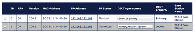
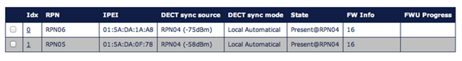
Go to the web interface of a base station and click on Multi Cell to see the status and the coverage values of every connected base, check the column DECT sync source to know the value.
Repeaters
Go to the web interface of a base station and click on Repeaters to see the status and the coverage values of every connected Repeater, check the column DECT sync source to know the value.
Base station/ Repeater Placement Strategy
The antennas of the base stations are close to omnidirectional, thus it is not important how the base stations are directed and how they face each other. There is no single strategy for deploying base stations, but there are some recommendations:
- In the Corridors: base stations/Repeater should be deployed vertically, preferably in the corridor intersections so that the propagation follows the corridor patterns/curves. If there are high objects in the area, the base station/Repeater should be installed above them.
- Multi-storey Buildings: base stations and Repeaters can be installed on the opposite sides of the floors to cover the area floor-to-floor. The coverage design cannot rely entirely on floor-to-floor propagation; each case should be verified due to variations in local attenuation patterns
- Large Halls: base stations and Repeaters can be deployed in large halls that contain a central open space area with windows leading to other areas. This provides a good coverage for the rooms in the inner circle on all floors (e.g. hotels). In large halls, Base stations/Repeaters should be installed vertically in the middle of the space below the drop ceiling.
- Mounting Positions: when Base stations and Repeaters are mounted vertically on a wall, the radio coverage in front of these devices is twice as large as the coverage behind them. The base stations should always be mounted higher than the obstructive objects in the area – e.g. minimally 2m above the floor. Repeaters should be installed in the middle of the corridors and small rooms.
- Metallic Structures/Objects: base stations and Repeaters should not be deployed near large metallic objects
- Reinforced Concrete Structures: these structures create a high attenuation factor inside the building. They reduce the radio coverage range of the Base stations and Repeaters thus a higher number of base stations or Repeaters are required in the building. Lighter types of construction materials require fewer base stations since attenuation figures are considerably lower.
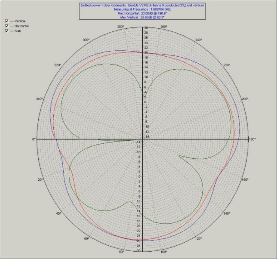
Radiation pattern - base optimal position for optimal coverage
Here is radiation pattern, measured when the unit is in an upright position. Antenna 0 is the right antenna seen from the back of the base station. If you print the pattern out on a paper and place a base station in the center you can see the radiation pattern:
Antenna 0:
Antenna 1:
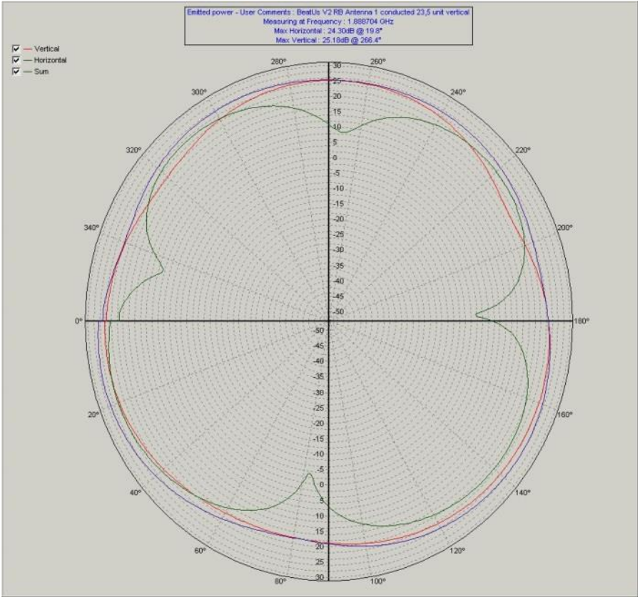
From the radiation pattern it can be seen that the optimal position of the base for optimal coverage is upright position. When base is deployed this position must be considered as it is optimal for cell coverage between base chains and handset usage.
In case the upright position is not possible it is important to again study the radiation pattern.
In case the base is horizontally positioned, the optimal radiation pattern between bases is when bases are placed side by side in the chain.
A doughnut shape radiation pattern means that the radiation is mainly concentrated on the sides of the Base and the radiation levels at the top and at the bottom are from -10 to -15dB lower.
Base station and repeaters connection and overview
Packing lists
W-AIR Base:
- Mounting screws x 2 and anchors x 2
- Plastic stand x 1
- Base station unit x 1
W-AIR Base Outdoor:
- Enclosure 175x250x75mm with some pre-installed parts:
- RJ45 cable gland + O-ring + Counter Nut x 1 set
- Ventilation Device x 1
- Wall mounting lugs x 4
- Metal bracket x 1
- Plastic plate x 1
- Base station unit x 1
W-AIR Repeater:
- Power adapter x 1
- Repeater unit x 1
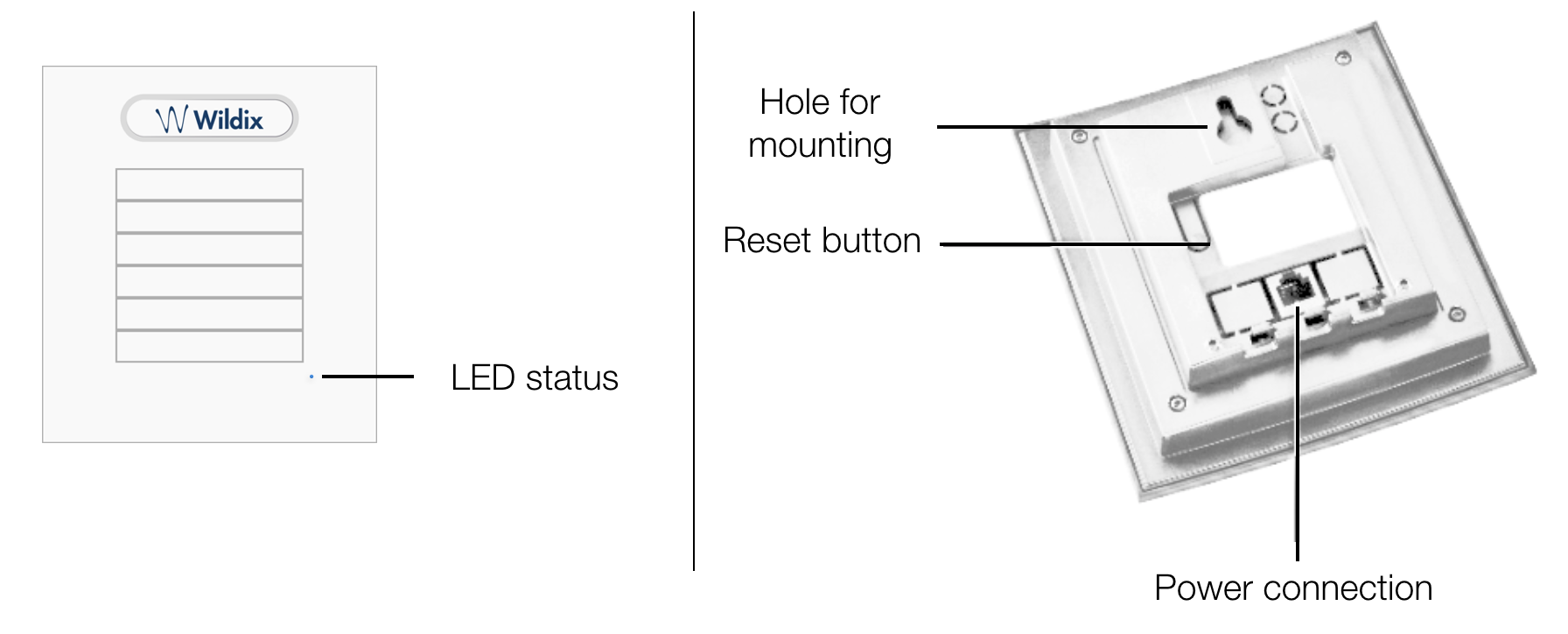
Base stations mounting, connection and reset
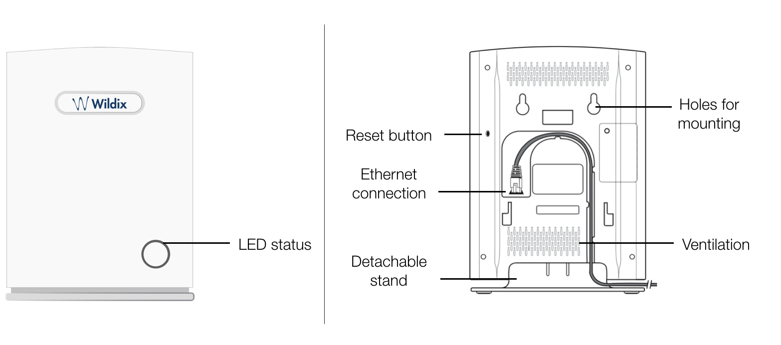
Reset a base station: press the Reset button on the back side for more than 2 seconds.
LEDs of the Base Stations
- LED blinks purple when a base is rebooting
- LED blinks red when a base reports a configuration error
- LED remains solid blue if a base is configured and registered to the Wildix PBX
Mounting instructions
W-AIR Base
Mount the base unit as high as possible to clear all nearby objects (e.g. office cubicles and cabinets, etc.). Make sure that when you fix the base stations with screws, the screws do not touch the PCB on the unit. Avoid all contacts with any high voltage lines.
W-AIR Base Outdoor
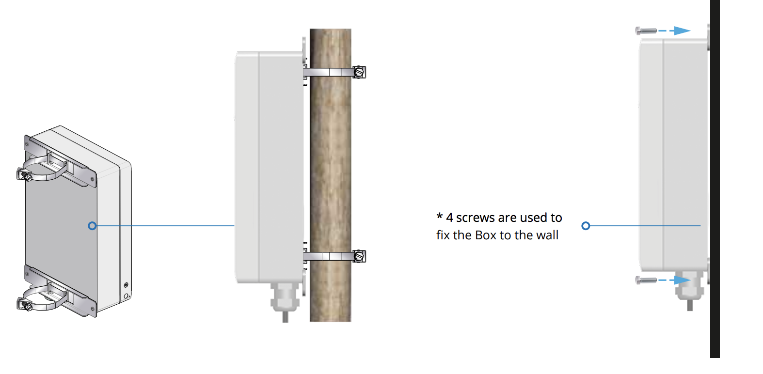
Find Base station IP
On the handset press “Menu” key followed by the keys: *47* to get the handset into find bases menu. Depending on the amount of powered on bases with active radios and the distance to the base it can take up to minutes to find a base.
- Use the cursor down/up to select the base MAC address for the base
- The base IP address will be shown in the display
The feature is also used for deployment.
Repeaters connection and overview
Repeater connection and reset
Reset a repeater: press and hold the Reset button on the back side for more than 2 seconds (LED turns solid RED and then GREEN with a double pulsation).
LEDs of the Repeaters
- LED blinks green with a double pulse during the first registration process
- LED blinks green during the connection process
- LED remains solid green when it is registered to a base station
- LED blinks green with a fast pulse when a phone connected to the Repeater starts a new call, during the conversation it blinks red
- LED becomes solid red if the Repeater fails to connect to the base station
- Double color flashing (red/green): Repeater is in recovery mode for one of the following reasons (try to re-assign Repeater to Base station):
- Repeater is locked to base/repeater without repeater mode activated
- Sync source base/repeater not found (Manual mode)
- Timeout during RPN allocation due to busy base/repeater
W-AIR Network configuration
Step 1. Provision base stations
For detailed instructions, refer to Provisioning of Wildix devices - Admin Guide.
Go to menu Devices of the WMS, click +Add and provision the gateway. Provisioned base stations appear in the table of Devices.
Step 2. Create a W-AIR Network
Important:
- W-AIR Network consists of one or more gateways that should belong to the same LAN or connected via VPN (without NAT). A base station can be a part of a W-AIR Network only if is reachable by other base stations. W-AIR cells exchange the network packages; in order to ensure the sync in case the packages are bigger than 1500 bytes, the network must correctly process “UDP fragmentation”
- In order to be able to configure a W-AIR network, an NTP server is necessary. To configure the gateway to use the NTP server of the PBX, select the gateway and click Edit, then enter the PBX IP address into the line “NTP Server” and click Save.
- In case you add a base station that previously functioned as a separate base station or belonged to a different W-AIR network, it’s necessary first to delete the base station, reset it and add it again to the WMS.
Follow the steps below:
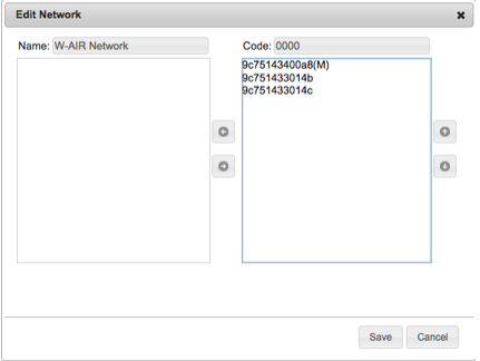
- Go to the WMS menu Devices → W-AIR Networks → click Add
- Enter the name Name for your W-AIR Network
Select the gateways from the list on the left and move them to the list on the right
Limitation: it is impossible to register a W-AIR Headset if the code of W-AIR network is different from "0000" (default code). Workaround: temporarily change the code to default one ("0000") , register and assign the Headset(s), and then change it back to custom one.
Click “Save”
The first base becomes the Main base of the network (M). The gateways make radio sync over the air with each other automatically to extend the work range if possible.
- Go back to the Devices Menu, select your base/bases and press “Configure/ Sync device” button
For CLOUD PBXs, you need to power off the base station and then power it on again (reboot the base station) to apply the new parameters!
Step 3. Register a W-AIR Handset
To register the handset:
- Verify that there is only one active W-AIR Network
- Go to the handset’s main menu
- Select Connectivity
- Select Deregister, enter 0000 as PIN, then press Yes
- Select Register, enter 0000 as Access code, then press OK
- The cordless phone is ready for a new login procedure
To unregister the handset:
- Log out (register to “unknown” account) by calling the Feature Code “Login” (“99” by default)
- Select “Deregister” in the “Connectivity” menu of the handset
- Enter the Pin Code “0000”, then press “Yes”.
Step 4. Assign a W-AIR handset to user
You can assign W-AIR handset to a user via the handset itself or via WMS (starting from WMS 5.04.20220309.1).
Assigning via the handset
- Switch on your phone and wait till the system assigns you an “unknown account” and the coverage indicator turns active
- Dial the Login Feature Code (“99” by default)
- Enter an extension number and PIN (= the first five symbols of the user WEB password)
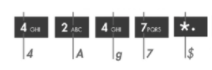
How to enter the PIN:
- The keys are alpha-numeric, they allow you to enter both letters and digits, to enter letters: press only once the key corresponding to the letter you need to enter (there is no difference between lowercase and uppercase letters)
- Press * (the star key) to enter any special characters present in the user password, including the symbol "#"
Example: PIN is 4Ag7$Zl@, you have to dial 4247*
Admin password is also accepted
Assigning via the WMS
Note: The support starts from WMS 5.04.20220309.1.
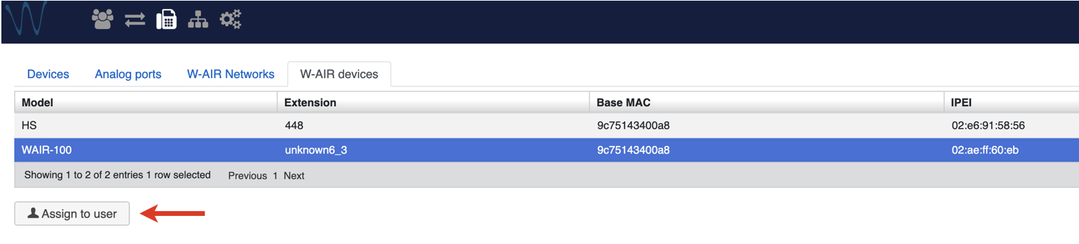
Go to WMS -> Devices -> W-AIR devices
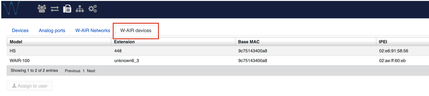
Choose the handset and click Assign to user
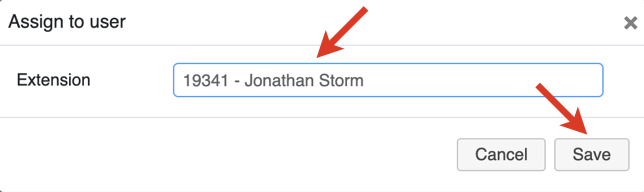
Enter user extension and click Save
Note: To figure out which handset received the assigned extension, you can dial this extension and see which handset rings.
To assign W-AIR handset to a different user:
- Choose the handset on the W-AIR devices tab -> click Assign to user
- Enter a different extension and click Save
To deassign a W-AIR handset:
- Choose the handset -> click Assign to user
Select “unknown” in the Extension field
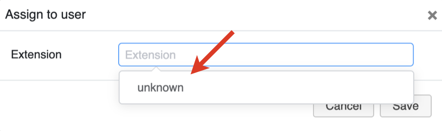
- Click Save
Step 5. Set up Repeaters
In multi-cell installation, up to 3 repeaters per base are supported:
- Up to 50 bases: 3 repeaters
- 50-125 bases: 1 repeater
- More than 125 bases: no repeater
Depending on the number of Bases (in case of multi-cell installation), you should specify the number of Repeaters on the web interface of the Base station (under Base station settings):
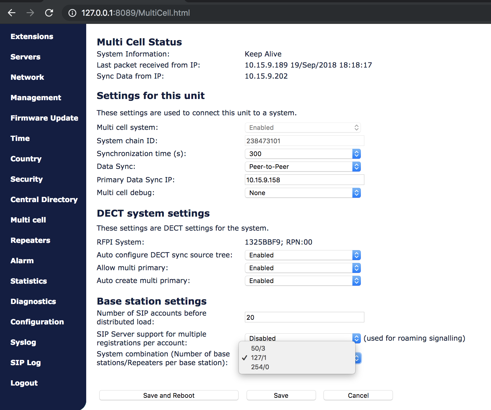
Proceed as follows:
- Find the IP of the base station that you want to repeat (on the WMS devices list)
- Access the base station's web interface, enter a username “admin” and a password that you can find in the WMS Devices menu in the “Password” field of the given base station.
- Select Repeaters in the menu and click on “Add Repeater”
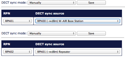
- Select Manually from the drop-down menu if it is present, then choose the Station ID (DECT sync source) where you want to connect the Repeater and confirm by pressing the Save button
- Reboot the Base station (go to Management menu and click “Save and reboot”). After the system reboots, go back to the base station’s interface
- Select Repeaters in the menu
- Select a Repeater(s) you want to add to the chain and click on Register Repeater(s)
- Now you have 5 minutes to turn on the Repeater(s)
- LED of the Repeater should turn solid green in several seconds, if it fails (solid RED) please repeat the steps after the reboot of the base station
Notes:
- If you have any problems with registering Repeater(s), reset it by pressing the Reset button on the back side for more than 2 seconds (LED turns solid RED and then GREEN with a double pulsation). Start the registration procedure again by following the last three points above.
- Repeater should be placed on a distance not less than 10 meters from its Base station.
- For a good conversation and a correct handover between Bases and Repeaters the dBm value should be between -75 and 0.
W-AIR Network deployment
Case 1: Sync chain with one Primary Base
The sync chain must always overlap with other Base stations in order to latch each other in sync.
Primary base is the one that performs the sync.
A maximum of 24 sync levels (Including the primary base) can be used in a deployment.
Secondary base stations or repeaters are connected to the Primary base through the synchronisation chain
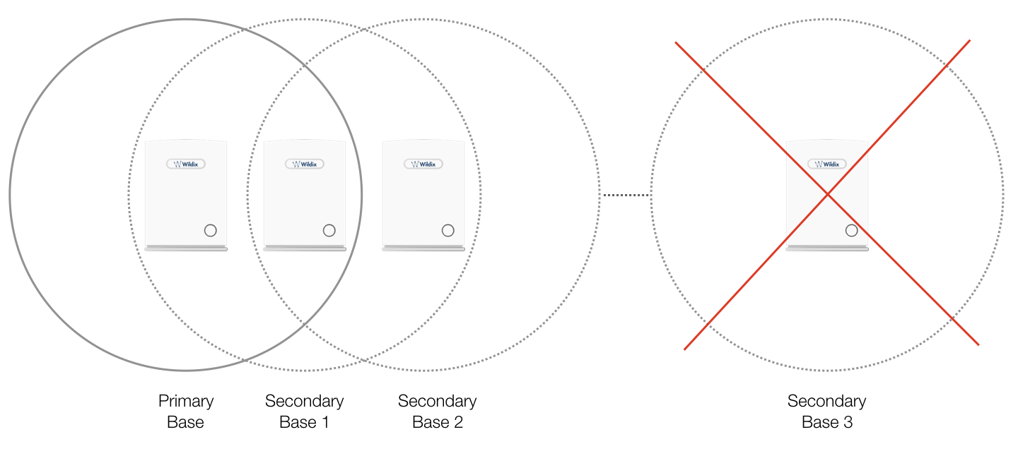
If one of the base or repeater units in the sync chain is broken or not working, then the units that follow the non-working device are cut off from the sync chain, and sync can be lost. In this case, handover between the two clusters is not possible.
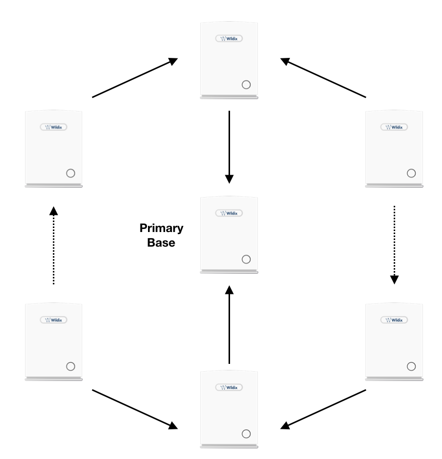
Bad deployment example:
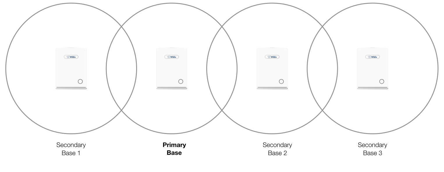
Good deployment example (Secondary Base 1 and 2 are at sync level 1, Secondary Base 3 is at sync level 2)
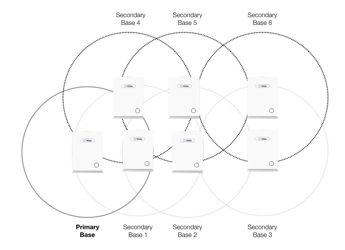
Case 2: Sync chain without alternative sync paths
A maximum of 250 base stations can be deployed in one setup (depending on the network requirement not all base stations should be chained).
A maximum of 24 sync levels can be used in any deployment.
Depending on the system setup, it is recommended to place the Primary base station in the middle of the building and to assign numbers/addresses, radio ID (RPN), etc. to each base station or repeater for easy identification.
Continuous line: Shows the primary sync paths, with the relevant bases chained in the multicell network.
Dotted line: Alternative sync paths.
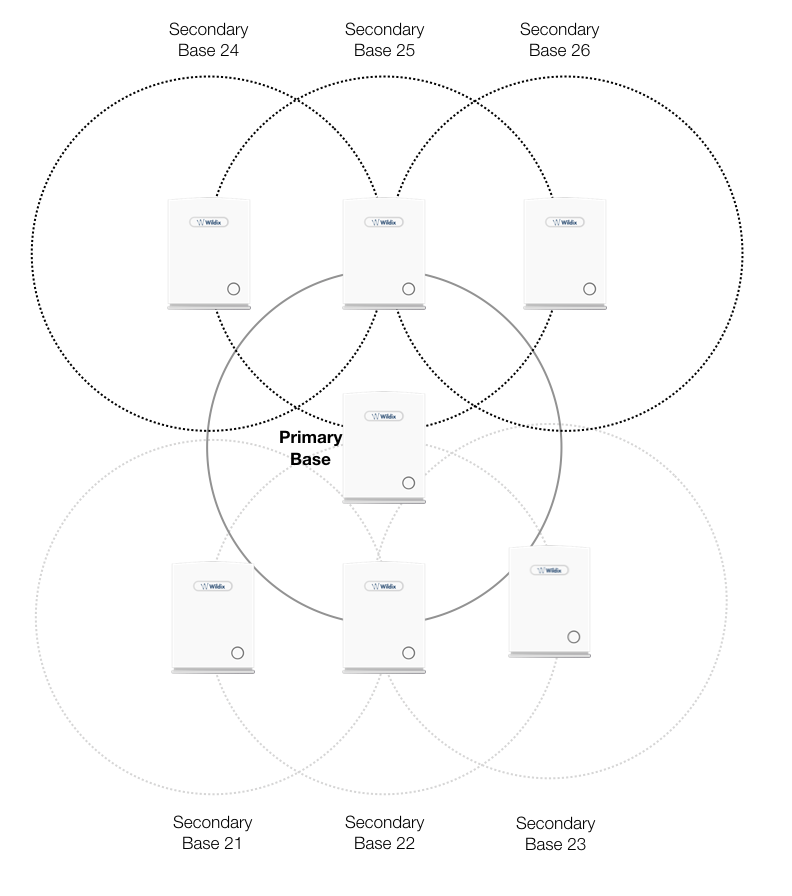
Case 3. Sync chain with alternative sync paths.
The scheme below shows a multicell network with alternative synchronisation paths. A failure of one base unit does not mean handset or users cannot perform handovers to other active cells.
If the Secondary Base 2 is down, the majority of user handovers can be performed via 3 other alternative cells (i.e. Secondary Base 3, 5 and 1) without any problems.
Take into consideration the following:
- Base 4 and 1 are Primary with alternative sync to the Primary Base.
- Base 5 is primary sync to Base 4 while alternative sync is Base 1 or 2.
- Base 3 is primary sync to Base 2 while alternative sync is Base 5 or 6.
In the scheme below:
- Base 24 is the primary sync to Base 25 while alternative sync is Base 20
- Base 22 is the primary sync to Base 20 while alternative sync is Base 21 or Base 23
Verify deployment
The actual sync RSSI may be read on the base station web interface. It is recommended to have a RSSI value better than/ equal to -75dBm, and never below 090dBm. Take a look at the DECT Chain Tree to check the solution you have decided to set up.
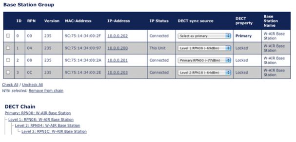
The DECT Chain Tree should correspond to the real Bases deployment (as in the following example)
The value shown in the “DECT sync source” field indicates the real dBm value.
Based on this value you can choose the best connection solution for your system, taking into consideration any obstacles present in the environment.
.png?version=1&modificationDate=1561708629000&cacheVersion=1&api=v2&width=359&height=250)
When you modify the DECT Chain Tree, you have to start the System Sync. This operation can take up to 10 minutes.
W-AIR Network auto roaming feature
Features:
- up to 250 offices/ base stations – 1000 handsets/ users in one DECT network
- redundant – all offices base stations are autonomous
- roaming – users can roam over all base stations/ offices
- user sign-on/ hot desking
- centralized phonebook with presence
Thanks to WMS Network up to 500 PBXs – HW, VM or Cloud PBXs – connect together and create a peer to peer Telephony network which is secure, synchronized. The base stations of the DECT network can be connected to any one of the PBX (with a secondary one as failover) and work even in case internet is not available. The handsets information is shared via IP service over the DECT gateways network.
Users can roam all over the base stations preserving their internal number. When a user moves between from office to another, location is automatically updated and the personal settings (forwards, call management rules) are retrieved. Users do not need the help of an administrator to start using an handset, the sign-on require to enter via IVR the phone number and personal pin code. It is easy to share the phone between many users as sign-on / sign-off operators require just a few seconds.
Requirements:
- layer 3 VPN over all sites
- support for UDP fragmentation (since MTU of packets is over 1500 bytes)
- base stations must be able to reach each other via IP
How-to:
- Enter the local IP address of the Primary Base Station into the field “Primary Base IP” (Devices -> W-AIR Networks -> "Edit Network")
- Connect all the base stations and add them to the WMS Network Server PBX
- Set as DNS server for each base station (in Devices -> “Edit” device) the PBX to which the base station must be connected
- Set as DNS name “auto.wildixin.com” in the field “SIP Proxy” (Devices -> W-AIR Networks -> “Edit” Network) to have all phones connected to the correct PBX (this is possible thanks to point 3)
Call Features
DND, Call forwarding, Paging, Call intrusion, Intercom
All the Call Features can be set up in WMS or Wildix Collaborations in User Settings, or otherwise, directly from the handset, by dialing the Feature Codes of the system.
Consult the guide Feature Codes and Pre answer Services - Admin Guide.
Ring tones
Ring tones set in Collaboration are not applied to W-AIR handsets. You can set ring tones via Dialplan "Set" application.
Consult Dialplan applications Admin Guide.
Call transfer, hold, call swap, conference call
These operations can be performed directly from W-AIR handset, consult the guide W-AIR DECT Handset for details.
W-AIR Handsets support only 2 calls/ channels, this means, when you have one active call and one call on hold, you can only transfer perform a transfer of the active call to the party which is on hold, or vice versa. You cannot transfer a call to some third party, because no more channel can be opened.
If you need to transfer a call to some third party when you have one active call and one call on hold, you can use in-call Feature codes (since it doesn't require opening a new channel): #8 for attended transfer and #9 for blind transfer. Consult Feature Codes and Pre answer Services Guide for detailed information.
Upgrade Procedure of W-AIR system
FW upgrade of Base Stations
When there is the new FW available, the base stations appear in blue in the Devices menu of WMS.
To upgrade the FW, select one or multiple base stations, and click “Configure/Sync”. Wait for several minutes, during the FW upgrade, devices are rebooted. As soon as the upgrade procedure is finished, the new FW version appears in the Devices menu of the WMS, the base stations are no longer marked with the blue color.
FW upgrade of Repeaters and Handsets
After the upgrade of the base stations, Repeaters and Handsets connected to the system download the new FW automatically. You can monitor the process of the FW upgrade from the base station’s web interface.
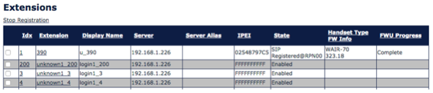
Repeaters
- Repeaters must be connected to be able to perform the upgrade procedure.
- Do not turn off or reboot repeaters manually during the upgrade: they restart automatically.
Go to the Base Station interface, menu “Repeaters”: During the reboot you can see the progress of the upgrade of the repeaters in the field “FWU Progress”. As soon as it’s finished, the “FWU Progress” displays “Complete”.
Handsets
New FW is downloaded automatically after the Base Stations have been upgraded. To complete the FW upgrade procedure of the handsets, the handsets must be placed into the charger.
During the procedure you can see the status of the upgrade of the phones, the procedure takes about 30 minutes. Go to the Base Station interface, menu “Extensions” (Go to tab “Handset” of “Extensions” menu - only for Base Station SB): During the reboot you can see the progress of the upgrade in the field “FWU Progress”. As soon as it’s finished, the “FWU Progress” displays “Complete”.
Alarms setting
Types of alarms
Alarm Button
This alarm is triggered by long-pressing (3 seconds) the red button on top of the handset.
Pull Cord Alarm
The Pull Cord alarm can be triggered by pulling a cord containing a magnet from the pull cord hole on the right side of the handset.
Running Alarm
To trigger the Running Alarm the handset needs to be shaken up and down for several seconds.
Man Down Alarm
The Man Down alarm is triggered if the handset remains in the position with an angle over 60 degrees with respect to the horizontal. The time for the handset to be still before the alarm is triggered can be set on base station web interface (read the next chapter 7.3. Set up emergency profiles)
No Movement Alarm
To trigger the No Movement alarm the handset needs to be in no movement. The timeout after which No Movement alarm is triggered is set on the base station web interface.
Set up emergency profiles
Go to the menu “Alarms”. In this menu eight different alarm profiles can be configured. The parameters that can be configured are:
Profile Alias: A user friendly name to help identify the different profiles when selecting which one to enable for individual handsets.
Alarm Type: The type of event that triggers an alarm. The options are: Disabled, Man Down, No Movement, Running, Pull Cord, Emergency Button.
Alarm Signal: Call. The alarm is made as an outgoing call to the emergency number preconfigured for the extension.
Stop Alarm from Handset: Enable/Disable. The possibility to cancel an alarm from the handset.
Trigger Delay: The timeout before the phone starts showing pre-alarm warning. If set to 0, the alarm is sent immediately (max. value is 255 sec.).
For Man Down alarm, add the default delay of 6 seconds which is the time needed for the alarm detection (e.g. if set to “0”, alarm is triggered after 6 sec, if set to “30”, alarm is triggered after 36 sec.)
Stop Pre-Alarm from Handset: Enable/Disable the possibility to cancel the pre-alarm from the handset.
Pre-Alarm Delay: The timeout during which the pre-alarm warning is displayed until the actual alarm is sent (max. value is 255 sec.)
Howling: Enable/Disable the howling of the handset when the alarm is triggered.
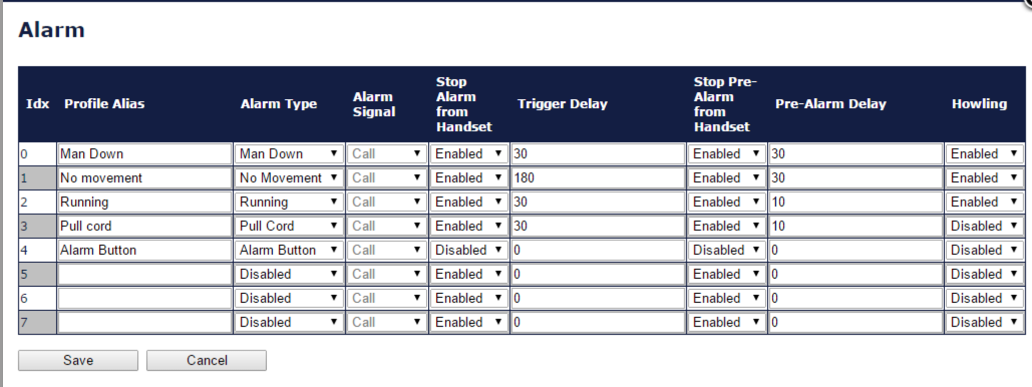
After you have defined the Emergency profiles, click Save to apply.
Assign emergency profile to handsets
- Go to the menu Extensions
- Click on the field “Idx” or “Extension” of the handset:
- The following window is displayed, allowing you to set up emergency settings:
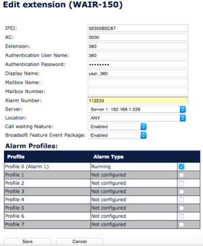
Modify the parameter “Alarm Number”: Enter the number to be called when the alarm is triggered from the handset
You can enter an extension number that must be called or customise the service by modifying the Dialplan in the WMS and to add the “Alarm Number” as a Called number into a Dialplan procedure.
Tick off the Profiles that you wish to enable for this handset
Click Save at the bottom of the page
Go to Management menu and click Save and reboot to reboot the base station and apply the new parameters